З 18.12.23 магазин в м.Дніпро за адресою вул.Новокримська 58 не працює.
Однак, наш інтернет-магазин відкритий для вас 24/7.
Усі місцеві замовлення можуть бути відправлені кур'єрськими службами.
Web Speech API is not supported by this browser. Install Google Chrome.
Voice input also works in Safari, Yandex, as well as mobile browsers Huawei, Opera and Samsung..
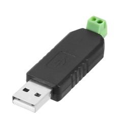
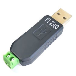
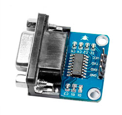
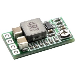
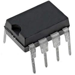
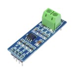
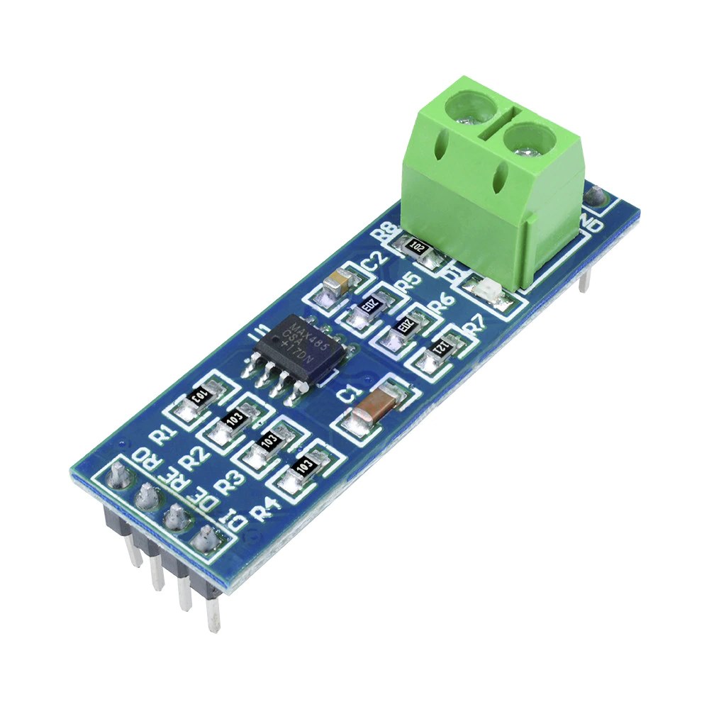
The UART TTL to RS-485 interface converter module, assembled on the MAX485 physical level converter chip, specializes in building local networks with two-way data exchange over fairly long distances. The RS-485 interface is most relevant in industrial production, in which equipment located in large areas can be located at significant distances from each other. The compact dimensions of the board are conducive to the integration of the UART-RS485 module into a variety of devices, starting from the smallest designs. The RS-485 converter module can be used with computing platforms, including Arduino, Teensy, PyCom, ESP, STM, Raspberry Pi and others, as well as any other control device equipped with an internal or external UART asynchronous serial communication bus.
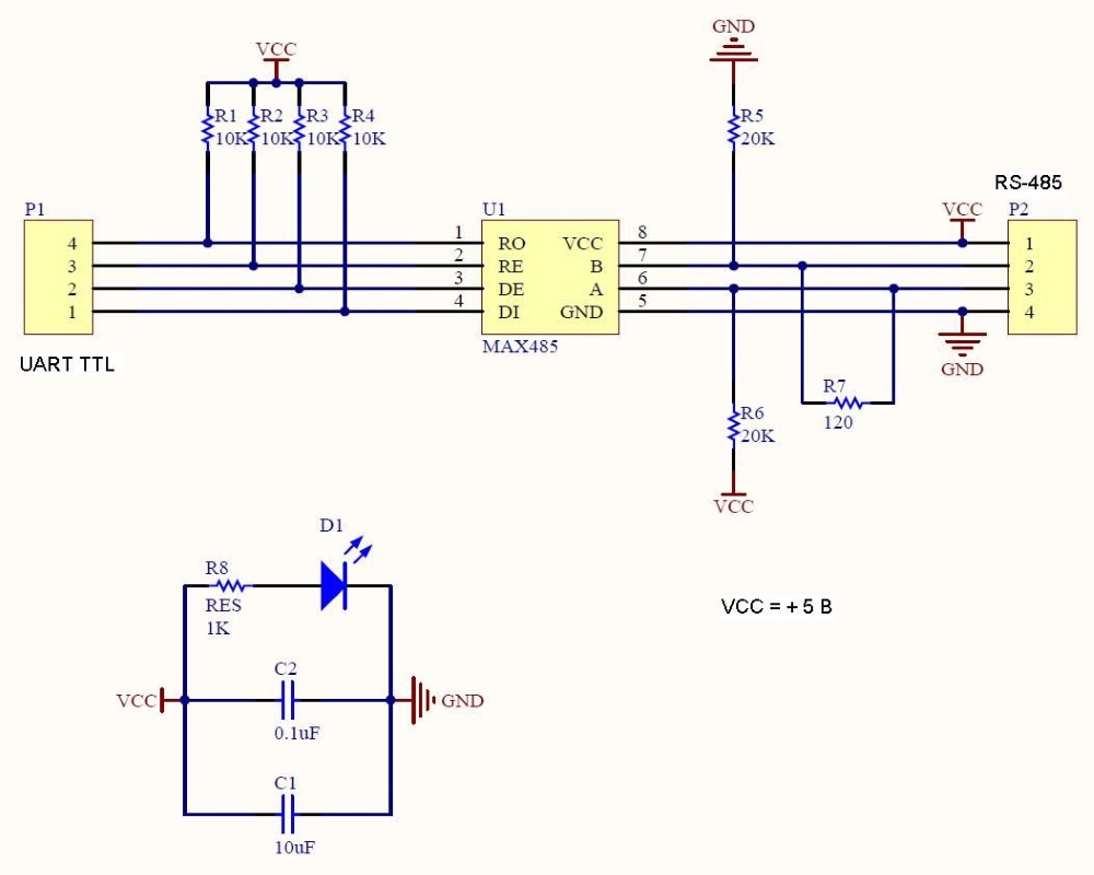
The RS-485 interface does not require separate transmission clock pulses. RS-485 is based on the principle of differential transmission of binary information from one device to another. Bidirectional signal transmission between devices with RS-485 interface is carried out via two twisted wires. The third "common" wire is often used to improve the quality of communication and stabilize the operation of the interface, which equalizes the ground potential of devices connected to the RS-485 bus, but is not mandatory. In practice, the twisted pair cable with an average impedance of 100-120 ohms is considered the optimal cable for connecting nodes. The voltage level in lines A and B can vary from -7V to +12V (depending on the model of the transceiver and its operating voltage). Receivers of devices on the RS-485 bus are sensitive to the potential difference between lines A and B. When receiving a logical one, the potential difference at the input is positive (A is greater than B by at least 200 mV), when receiving a logical zero, the difference on the lines is negative (A is less than B at least 200 mV). A potential difference between A and B of less than 200 mV implies no signal. The RS-485 interface is limited by one condition - signal transmission for all active receivers is carried out by a single transmitter.
The construction of complex networks within RS-485, including branching segments or placing nodes at much greater distances, requires the addition of special signal amplifiers and repeaters (repeaters). At a high transmission rate between nodes, on long sections of the line, signal distortion may occur due to the effect of its back reflection. To dampen signal fluctuations, at the ends of each long section of RS-485 networks, so-called terminators are installed - terminating resistors with a rating equal to the characteristic impedance of the connecting cable.
Pin assignment:
"VCC" - Module power supply, 3.3 - 5V.
"A" - Non-inverted RS-485 input of the receiver, non-inverted RS-485 output of the transmitter.
"B" - Inverted RS-485 input of the receiver, inverted RS-485 output of the transmitter.
"GND" - General, 0V.
"RO" - Receiver output (to RX UART pin).
"RE" - UART output control of the receiver. Active when signal is low.
"DE" - Transmitter UART input control. Active when the signal level is high.
"DI" - Transmitter input (to TX UART pin).
The RE and DE control pins on the MAX485 transceiver provide the host (controller) with the ability to receive or transmit data in independent communications. Based on the requirements of the recommended RS-485 standard for the method of information exchange in half-duplex mode, and taking into account the necessary level of logical pulses to enable or disable the receiver and transmitter, separate use of control contacts is in most cases impractical. It is quite possible to combine both contacts into one and control the process of receiving / transmitting data using one digital port of the controller.
Only registered users can leave feedback and ask questions
The data presented in the product description are for reference only and may differ from those indicated by the manufacturer.
To carry out technical calculations and obtain the exact parameters of the goods, use the datasheets from the manufacturer's website.
If you need additional information, or you found an error in the description, or have other questions about this product, then our manager will help you: Денис - Днепр
unknown


 The data presented in the product description are for reference only and may differ from those indicated by the manufacturer.